[Source : GPS World]
Installed GPS navigation systems are becoming popular options for new car buyers. and many aftermarket, portable, and PDA- or cell phone–based systems are available in the marketplace.
A basic GPS navigation system can provide continuous, accurate navigation, except when the GPS signals are blocked by buildings, tunnels, or other obstructions or when multipath or interference reduces position accuracy. A factory-installed system might include additional sensors such as an odometer or gyroscope to provide dead-reckoning navigation when GPS signals are lacking.
Another aid to accurate navigation is map-matching in which the computed position fix is snapped onto the nearest road. However, depending on the fix error and the density of the road network, the system may or may not snap the fix onto the correct road. In this month’s column, guest authors Syed and Cannon examine a novel technique that tightly integrates information from accurate maps with raw GPS and gyro data to determine a vehicle’s position. Using classic statistical theory and fuzzy logic algorithms, the technique improved vehicle navigation accuracy in an urban canyon setting by more than 30 percent. — R.B.L.
The confluence of wireless technology and GPS has led to the development of a new set of applications to serve the location-based needs of users. These applications are popularly known as location-based services, and a major portion of the location-based services market deals with applications using in-car navigation systems. These systems supply vehicle-position information for applications to provide guidance to nearby points of interest, advise on current traffic or weather conditions, and even generate location-based advertising.
Progressive industry leaders are building solid foundations to support well-conceived solutions for new location applications and value-added services. The other strong impetus for the development of location-based services comes from the United States Federal Communications Commission’s Enhanced 911 mandate, which directs that all mobile phones be located for 67 percent of 911 calls with an accuracy of 100 meters for network-based technologies and 50 meters for handset-based technologies.
A key to the success of location-based services applications is accurate georeferencing of the position output obtained from a navigation system. Georeferencing involves relating the position to a map database to identify the road on which a vehicle is traveling. This procedure is called map matching. Systems that combine navigation and map data need the following characteristics to be effective and broadly used: affordable cost, accuracy of approximately 20 meters (at a 95-percent confidence level), automatic initialization without any input from users, effective display of position and location-based information, and a reliable map database.
In this article, we outline some of the challenges of positioning in urban areas and the problems that can occur when attempting to overlay inaccurate positions on a map. We introduce a new map-aided navigation technique, which integrates raw GPS measurements and map data, and provide some results from field tests to show the increased level of reliability when these two data types are integrated tightly.
Challenges in Urban Canyons
A vehicle-navigation system comprises a positioning subsystem and a map database. The positioning sensor can either be a dead-reckoning system or an autonomous system such as GPS or another global navigation satellite system (GNSS) or even a system based on wireless techniques such as cell identification, signal time of arrival, or signal angle of arrival. Wireless techniques generally are too coarse to be used for vehicle navigation, and dead-reckoning systems suffer from error accumulation over time. GPS has become a popular choice for vehicle navigation because of its 24-hour-a-day availability, free-of-charge use, autonomous nature, and high accuracy. However, GPS suffers from line-of-sight issues, which make it less effective in locations such as urban canyons where satellite availability is low due to signal blockage from high-rise buildings. In addition, multipath signals arising from building reflections and other interference effects can introduce large errors into the navigation solution.
Thus, the accuracy of GPS, as well as that of other positioning systems, may be limited in urban canyons. In addition, the task of vehicle location is further complicated in urban canyons because of the increased road network density.
To tackle the issue of signal availability, manufacturers have developed high-sensitivity GPS receivers. These receivers acquire and track weak signals by lowering the minimally useful signal-to-noise ratio, whereby the sensitivity can be increased by as much as 15 dB compared with a conventional GPS receiver. Although the measurement availability increases by using a high-sensitivity GPS receiver, the corresponding noise and errors also become magnified.
Dead reckoning and GPS have complementary characteristics that are in excellent synergy, because GPS provides an absolute position that generally is of good accuracy and dead reckoning provides highly accurate changes in position but needs an absolute reference. However, in the case of low-cost dead-reckoning sensors (such as low-cost accelerometers, gyroscopes, and differential speed-measuring sensors), the errors grow quickly in the absence of GPS. In addition, an erroneous GPS position may cause the system to (re)initialize which in turn can lead to large errors in the navigation solution. Thus, low-cost dead-reckoning sensors and high-sensitivity GPS receivers generally cannot provide the necessary accuracy for navigation in urban canyons where correct mapping of the resulting position to a road network is a requirement.
Map Matching
In general, vehicles travel on roads, and this condition puts special constraints on the vehicle-navigation problem. If both the maps and the positioning system were ideal, then the output from the system would indeed lie accurately on the correct road segment at all times. But in real-world conditions, the various noise sources affecting the signals and the instrumentation used by the positioning system, along with the map inaccuracies, result in the estimated position not necessarily being overlaid onto the road network. Map matching can be defined as the identification of the correct road segment followed by the determination of a position on it.
Conventionally, map matching is performed using either a geometric approach or a statistical approach. Geometric map matching, as the name suggests, is based on pure geometric criteria (for example, the closest road) identifying the road segment on which the vehicle is traveling. Statistical approaches, on the other hand, are based on curve fitting onto a road network based on the history of motion. (For the details of many conventional map-matching algorithms, see the "Further Reading".) If the position output is accurate, as in the case of a GPS position in open-area conditions, then conventional map matching will be accurate and reliable. But in the case of an urban canyon, where the accuracy of the navigation solution is degraded, map matching becomes very challenging. The drawbacks of conventional map-matching techniques can be summarized as follows:
- Nonoptimality in the navigation solution computation: Most map-matching algorithms do not deal with GPS computations and simply take the navigation solution from external GPS software without attempting to improve it with map information. This type of map matching is not the best way for obtaining a navigation solution in urban canyons because of GPS line-of-sight issues. Because the accuracy of GPS coupled with a low-cost dead-reckoning sensor is limited in urban canyons, the navigation solution already is corrupted before mapping it onto the road. This deficiency causes the incorporation of many sensor errors into the map-matched solution and may lead to the incorrect location of the vehicle on the wrong road segment.
- Lack of robustness in identifying the correct road segment: Map matching with a noisy navigation solution (even after removing the blunders) in a complex road-network environment is difficult unless using a robust road-identification technique. Many of the conventional algorithms lose track of the correct road segment when the sensor noise increases.
- Lack of navigational reliability monitoring: For successful vehicle navigation, especially in urban canyons, measurement outliers must be removed before computing a solution. This step can be achieved by monitoring individual pseudorange measurements for large multipath errors and other interference effects. The navigation solution then should be computed after excluding the faulty measurements. Most conventional map-matching algorithms do not automatically check GPS reliability.
Map-Aided GPS
An alternative method to compensate for navigation errors in GPS is to integrate the identified-road-segment information in the GPS computation model. This method involves two tasks: identifying the correct road segment using a map-matching algorithm and using the identified road segment in the GPS computation. One advantage of using map aiding instead of only using a dead-reckoning sensor is that quality map information provides a consistent level of uncertainty compared with the output from a low-cost dead-reckoning sensor whose level of uncertainty changes with temperature, vibration, and other factors. In addition, the tight integration of GPS with a map provides a better way of detecting outlier data in the GPS measurements, because the dead-reckoning sensors themselves may have failures that could result in accepting erroneous measurements and rejecting useful measurements when sensor data are used for reliability monitoring.
We have developed a new methodology that combines GPS positioning, dead reckoning, and map matching. We call it map-aided GPS (MAGPS). The goal of this technique is to estimate an accurate navigation solution that can be used to identify the correct road segment on which a vehicle is traveling. This road segment then will help to determine an accurate navigation solution at the next epoch. The input data to the system comes from a low-cost dead-reckoning sensor (a gyro), a high-sensitivity GPS receiver, and a map database.
The main features of the approach are:
- Tight integration of map information with GPS: The novel feature of this approach is implementation of map constraints in the GPS measurement model, which comprises pseudorange and Doppler data, as opposed to computing the GPS solution independently of the map information.
- Robust map-matching framework based on fuzzy logic: The advantages of using fuzzy logic are the simplified computation model and increased tolerance to high noise and contradictory information. When used properly, a fuzzy inference system generates precise information from noisy and contradictory input.
- Map-based reliability checking of GPS measurements: The system algorithm uses map information to remove GPS measurements that have large errors caused by multipath and cross-correlation effects (which can occur when using GPS in weak-signal environments). We used a multiple-outlier detection technique based on a separation-of-measurement approach. Such constraints also can be used effectively in other suboptimal, less memory-consuming reliability algorithms.
Map-Matching Framework
The purpose of the map-matching framework is to identify and subsequently track the road segment on which a vehicle is traveling. The MAGPS approach deals with a linear representation of the road segments, in which any road curve is represented in two dimensions by a set of piece-wise linear segments. The algorithm works in two modes referred to as first-fix mode and tracking mode. The system initializes itself in first-fix mode, and it reinitializes itself in this mode whenever it loses track of the vehicle position. After the system is initialized, the algorithm switches to tracking mode. Tracking mode uses the vehicle motion history to track the correct road segment in computing the navigation solution. The primary role of the gyro in the system is to provide information about turns taken by the vehicle to the fuzzy inference system. Map aiding for the navigation solution computation is applicable only in the tracking mode after the determination of the correct road segment.
First-Fix Subalgorithm. System initialization is performed by relying entirely on GPS measurements because a vehicle-motion history is unavailable. The position can be determined after checking the internal consistency of the pseudorange measurement based on a data-snooping method. A separation-of-measurement approach eliminates multiple outliers. The fuzzy inference system then accounts for the history of the position proximity to the road segment and the similarity of the vehicle’s velocity direction with the road segment orientation when making a decision about the identified road segment.
Tracking Mode. In the tracking mode, the determination of the correct road segment and the vehicle’s location on it are based on the history of the vehicle’s motion from previous epochs. The first step in tracking mode is to observe the distance of the current map-matched position from the approaching end-of-the-road segment. If the distance to the intersection exceeds a threshold, then an algorithm will identify the current segment as the identified segment at the next epoch. However, if the distance from the intersection is small, then the gyro-heading output is observed and a segment concurrent to the approaching intersection is selected as the identified road segment based on the difference between the heading change and the angle between the current and concurrent segments.
These concepts are translated into fuzzy rules in a tracking-mode fuzzy inference system to track the road segment. After determining the road segment, the system finds a vehicle’s position using map-aided reliability monitoring, which excludes the pseudoranges that have outlier errors.
MAGPS Measurement Model
![]()
Figure 1 Piece-wise linear representation of a road segment with two nodes (φ1,λ1 and φ2, λ2) and the vehicle location (φ , λ)
A road segment in the MAGPS approach is represented by the coordinates of the nodes, which are shown on a sample representation of a road segment in Figure 1.
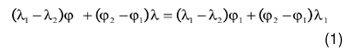
If (φ 1 , λ 1 ) and (φ 2 , λ 1 ) are the coordinates of the end points, then any point on the road segment satisfies Equation 1 — the equation of a straight line.
This relationship can be used as an additional constraint in the GPS-measurement model, as shown in Equation 2. Because the center-line accuracy of the road map used in our research was approximately 5 meters or less, this constraint can be used effectively to monitor the reliability of GPS measurements.
We have
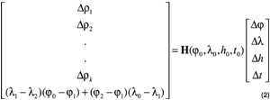
where (φ 0 , λ0 , h0, t ) are the assumed latitude, longitude, height, and receiver clock bias; Δρ ithe i-th-pseudorange misclosure corresponding to an assumed position and receiver clock-bias solution; (Δφ, Δλ,Δ h , Δ t) are the corrections to the assumed latitude, longitude, height, and receiver clock bias; and H(Δφ 0, Δλ 0 , Δ h 0 , Δ t 0 ) is the design matrix for GPS position computation linearized about the assumed coordinates.
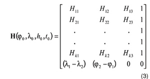
This matrix is the Jacobian of the pseudorange-measurement equation (whose elements are represented as Hii in Equation 3 below) with the last row derived from Equation 1.
If a constraint is imposed on the velocity to lie along a road segment direction, then the northing and easting components of the velocity should satisfy Equation 4.
![]()
where K lat | long is the ratio of the distance between a unit change of longitude and a unit change of latitude, ( v n , v e ) is the velocity in the north and the east directions, and R 1 is the condition equation that constrains the horizontal velocity components along the road direction.
The resulting velocity measurement model is given by Equation 5:
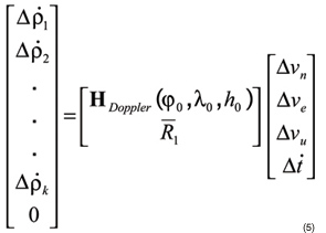
where (Δ v n , Δ v e , Δ v u Δ t ) are the unknown speeds in the north, east, and vertical directions and receiver clock drift; Δ ρ i is the i -th range-rate measurement; and H Doppler (φ 0 , λ 0 , h 0 ) is the design matrix relating range-rate measurements to the velocity and receiver clock-drift corrections.
In summary, the three basic steps involved in the MAGPS navigation algorithm are:
- Initialization of the vehicle on the road segment using the first-fix mode. Outliers are eliminated in this step using GPS stand-alone reliability checking based on a data-snooping method.
- Use of the identified road-segment information in the MAGPS measurement model to determine position and velocity. The position is determined from pseudorange measurements using the least-squares method with reliability checking using the data-snooping method with identified road-segment constraints. Velocity is derived from a Kalman filter with a constant-velocity dynamic model. Outliers in this case are detected using innovation testing. The final map-matched position is determined by assigning suitable weights to the pseudorange-based position and the velocity-propagated position. If the algorithm is unable to compute an outlier-free position solution based on pseudoranges, then it propagates the solution based on a Kalman filter–derived velocity solution.
- Reinitialization. If the uncertainty in the position solution grows such that the vehicle position may be in error by one block on the road network, the system is reinitialized as discussed in the first step.
Results
We tested the proposed algorithm by postprocessing data collected in downtown Calgary, Alberta, Canada, in an urban canyon environment. We compared the MAGPS approach with a conventional geometric map-matching approach. This conventional approach is based on pure geometric criteria such as position proximity to a road segment and velocity direction.
Figure 2 Position output fixes from (A) high-sensitivity (HS) GPS real-time algorithm solution
and (B) least-squares (LSQ) postprocessing of pseudoranges
Because the aim of a map-matching algorithm is to locate a vehicle on the correct road segment, we can assess its performance in terms of the correct and false fixes on the road segments. The percentage of correct/false fixes for a particular approach is defined as the number of correct/incorrect fixes out of the total number of test epochs for which the corresponding solution was available. An unfixed solution occurred when the algorithm did not match the position of any road segment. Because the correct road segment was known throughout the test, we were able to generate these statistics for the entire test run.
Figure 3 GPS solution availability from a high-sensitivity (HS) GPS receiver
Figure 2 shows the position fixes obtained from the GPS receiver’s real-time navigation algorithm (internal solution) and the least-squares epoch-by-epoch postprocessing solutions determined from the GPS measurements. The figure shows that the internal solution is smooth with intermittent discontinuities, whereas the least-squares solution is discontinuous because it does not carry forward the solution history. Mapping the least-squares solution can become very challenging because the noisy solution is spread literally all over the map.

Figure 4 Position output fixes from (A) high-sensitivity (HS) GPS real-time algorithm solution
and (B) least-squares (LSQ) postprocessing of pseudoranges
Figure 3 illustrates the solution availability from the high-sensitivity GPS receiver used in the test. The figure shows that the solutions from the receiver’s internal algorithms have higher availability (98.9 percent) than that provided using least-squares processing (74.6 percent), which needs a minimum of four satellites for computation of the navigation solution. The availability in the case of the high-sensitivity GPS receiver is approximately 40 percent higher than a conventional GPS receiver, which we used in the test for comparison. Higher availability leads to enhanced map matching because of the continuity in the navigation solution.
Figure 5 Graphical representation of the performances of different map-matching approaches
using the high-sensitivity (HS) GPS measurements
Figure 4 shows the map-matched position output obtained using the MAGPS approach and the geometric approach using the least-squares GPS solutions. Figure 5 graphically shows the performances of the two approaches.
We can draw the following inferences about the performance of the two map-matching approaches presented above:
Conclusions

Further Reading
We have introduced a new approach for vehicle navigation in urban canyon conditions using a model that tightly integrates raw GPS data and map information. We tested our approach by postprocessing collected data on a general-purpose computer. However, with the growing power of GNSS microprocessors and the ease of interfacing them with map data, MAGPS may become a viable and very reliable technique for vehicle navigation in urban canyons. The motivation for this research comes from the fact that although high-sensitivity GPS increases availability, an algorithm is necessary for monitoring the reliability of measurements by detecting outliers. In this context, the map can provide useful constraints to detect and remove blunders in whatever estimation method is used.
The developed approach combines classic statistical theory with fuzzy logic techniques to tackle the vehicle-navigation problem. The road segment on which a vehicle is traveling is decided by a fuzzy logic inference system, which receives input from a high-sensitivity GPS receiver and a gyro. We used classic statistical theory to compute an outlier-free navigation solution, which is then used by a fuzzy inference system to determine the road segment on which a vehicle is traveling. This road segment, in turn, serves as a useful constraint to eliminate outliers that arise from the urban canyon environment. The system was tested in a downtown area, and the results show that the new approach improved performance by more than 30 percent in terms of locating a vehicle on the correct road segment.
Acknowledgments
The work discussed in this article was part of Salman Syed’s M.Sc. studies at the University of Calgary performed under the supervision of Elizabeth Cannon. The authors would like to acknowledge SiRF Technology, Inc., for providing the GPS receiver used in the research. They also would like to acknowledge the Auto21 Network of Centres of Excellence for financial support.
Manufacturers
The authors used a GPS receiver with SiRFXTrac software from SiRF Technology, Inc. (www.sirf.com/ and an ENV-05 piezoelectric gyroscope from Murata Manufacturing Co., Ltd. (www.murata.co.jp/
SALMAN SYED currently is a GPS engineer at SiRF Technology, Inc., Phoenix, Arizona. He obtained his M.Sc. in geomatics engineering from the University of Calgary in June 2005 and a B.Tech. from the Indian Institute of Technology, Bombay, in July 2002.
|
|

ELIZABETH CANNON is professor and head of the Department of Geomatics Engineering at the University of Calgary. She has worked extensively in various GPS-related areas and on the integration of GPS and inertial navigation systems for precise aircraft positioning.
"Innovation" is a regular column featuring discussions about recent advances in GPS technology and its applications as well as the fundamentals of GPS positioning. The column is coordinated by RICHARD LANGLEY of the Department of Geodesy and Geomatics Engineering at the University of New Brunswick, who appreciates receiving your comments and topic suggestions. To contact him, see the "Columnists" section of this issue